
Why Do Tube Fittings Leak? 10 Common Causes and How to Prevent Them
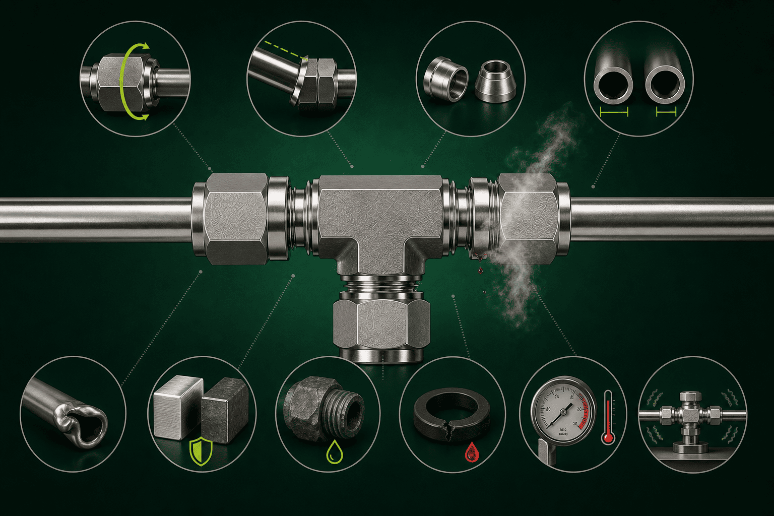
This technical document outlines the critical tolerances, assembly sequences, and diagnostic practices for high-pressure fluid instrumentation systems manufactured to industrial standards.
Why Do Tube Fittings Leak? 10 Common Causes and How to Prevent Them
Tube fitting leaks are one of the most frustrating problems in fluid and instrumentation systems — and one of the most preventable. When a system fails its pressure test or develops a leak in service, the instinct is to blame the fitting. But in my experience supporting customers across oil and gas, semiconductor, chemical, and industrial gas applications, the fitting is rarely the root cause1. The real problem usually started much earlier.
Most tube fitting leaks trace back to decisions made before the fitting was ever installed2. Selection mismatches, installation shortcuts, and unanswered specification questions are responsible for the vast majority of field leaks. If you can identify these risks at the procurement and engineering stage — rather than after pressurization — you can eliminate most leak failures before they happen.
Understanding the causes of tube fitting leaks is really a pre-installation risk exercise. Each of the ten causes below maps to a decision point: something you can check, verify, or confirm before the fitting goes into the system. Think of this article as a pre-commissioning checklist framed as a diagnostic guide.
Is Improper Installation the Leading Cause of Tube Fitting Leaks?
Improper installation is, without question, the category that generates the most complaints and support questions we receive. It's not always a careless technician — it's often a trained professional who was never given the right instruction for compression-style fittings specifically. That gap creates predictable, repeatable failures.
Compression tube fittings rely on precise ferrule deformation during initial make-up. Under-tightening leaves the ferrule partially swaged and unable to seal. Over-tightening deforms the tube or fitting body beyond recovery. Neither error is immediately obvious — both are discovered at pressure test.
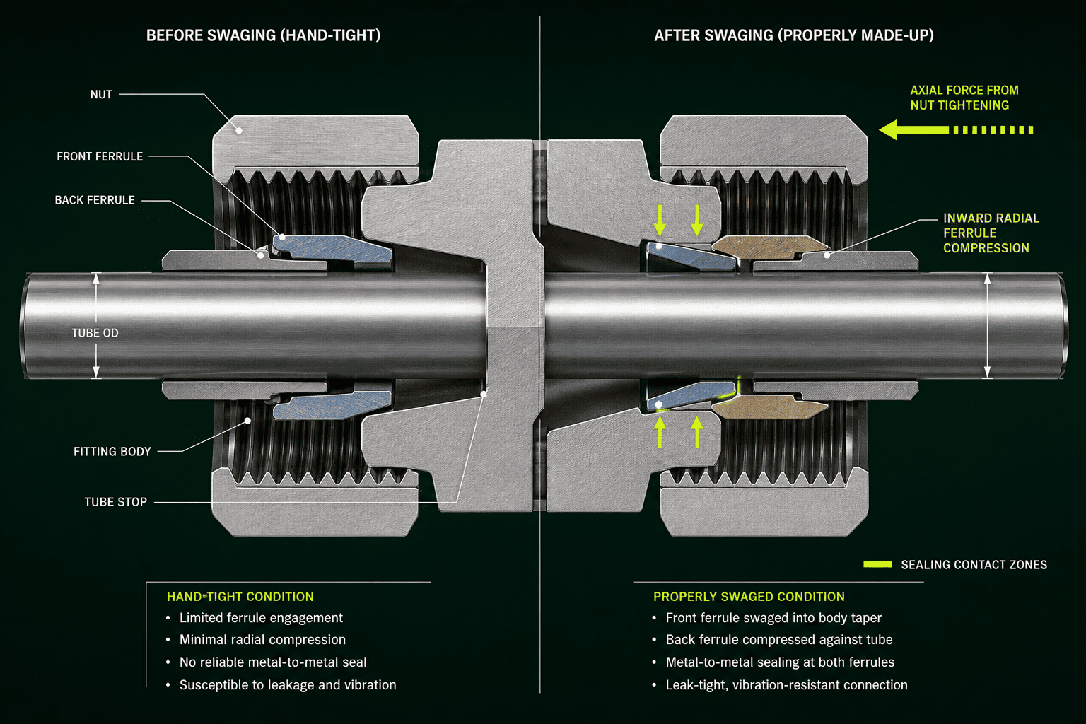
Most installers understand torque. What they don't always understand is that compression fittings use rotation count — not feel — as the installation standard.
Cause 1: Ignoring the 1.25-Turn Rule
This is the single most common installation error I encounter in technical support conversations. Almost every major compression fitting standard specifies an initial make-up procedure: finger-tighten the nut until snug, then advance it a specific number of turns — typically 1.25 turns3 for most standard tube fitting sizes.
This isn't a suggestion. It's the mechanical basis for proper ferrule swaging.
Here's why it matters:
- The ferrule is engineered to deform at a calibrated compression angle4
- 1.25 turns produces the correct bite depth into the tube OD
- Less than that leaves the ferrule under-swaged — the seal is incomplete
- More than that can thin the tube wall, crack the back ferrule, or seize the assembly
Customers who "tighten by feel" almost always under-compress. The fitting feels snug before the ferrule has fully engaged, and the installer stops there. The system passes a low-pressure leak check, then fails under operating conditions or thermal cycling.
What to verify before installation: Confirm your installation team has the make-up specification for the specific fitting brand and size being used. Don't assume the procedure is universal — it varies slightly by manufacturer and by tube OD.
Cause 2: Misaligned or Bent Tube Entry
A tube that enters the fitting body at an angle, or that hasn't been fully inserted before nut tightening, creates an off-center ferrule bite. This results in an incomplete seal on one side of the tube circumference.
Check these steps every time:
- Cut the tube square — no angled cuts
- Deburr the tube end inside and outside
- Insert the tube fully to the tube stop before tightening
- Hold the tube against the stop while beginning nut rotation
Partial insertion is especially common when installers are working in tight spaces and can't visually confirm full seating.
Cause 3: Reusing Single-Use Ferrules
Compression ferrules are designed for a single installation5. Once swaged, the ferrule geometry is permanently altered. Reinstalling a used ferrule on the same or a different tube rarely reproduces the original seal geometry.
Many customers reuse ferrules during system modifications or maintenance cycles without realizing the risk. If a fitting is disassembled for any reason, replace the ferrule set before reassembly. This is a procurement cost, not an engineering judgment call.
Does Tube Specification Mismatch Cause Tube Fitting Leaks?
Tube specification mismatch is the category that surprises customers the most — because it's invisible at the point of purchase. The fitting looks right. The tube looks right. They go together physically. But the seal fails at pressure. In our technical support interactions, this situation often leads to an incorrect conclusion that the fitting is defective.
A tube fitting is dimensionally engineered for a specific tube outside diameter (OD), wall thickness range, and material hardness. If any of these variables falls outside the fitting's design envelope, the ferrule cannot form the correct seal — regardless of how carefully the fitting is installed.
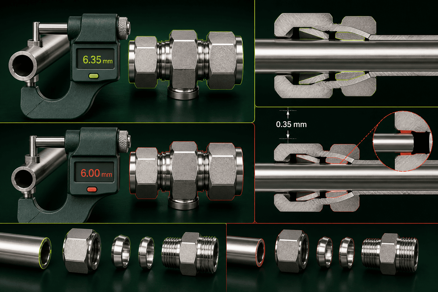
The mismatch problem has three distinct layers, and each one is a procurement decision point.
Cause 4: Inch vs. Metric OD Confusion
This is more common than it should be. A 1/4-inch tube fitting is designed for 6.35 mm OD tubing. A 6 mm tube fitting is designed for 6.00 mm OD tubing. That 0.35 mm difference is enough to prevent proper ferrule engagement6.
Customers operating across international supply chains — or mixing legacy and new-build equipment — frequently encounter this mismatch. The tube and fitting come from different sourcing streams and carry different dimensional standards.
| Nominal Size | Inch OD (mm) | Metric OD (mm) | Difference |
|---|---|---|---|
| "1/4 inch" | 6.35 mm | 6.00 mm | 0.35 mm |
| "3/8 inch" | 9.53 mm | 10.00 mm | 0.47 mm |
| "1/2 inch" | 12.70 mm | 12.00 mm | 0.70 mm |
Procurement action: Specify tube OD standard explicitly on every purchase order — not just nominal size. Confirm that your tube supplier and fitting supplier are working from the same dimensional standard.
Cause 5: Wall Thickness Outside the Fitting's Range
Every compression fitting is rated for a range of tube wall thicknesses. A tube that is too thin will collapse under ferrule compression. A tube that is too thick won't allow the ferrule to bite correctly.
This variable is almost never checked during procurement. Buyers specify tube OD and material, but wall thickness is treated as a secondary detail. In reality, it directly affects whether the fitting can form a reliable seal.
Ask your fitting supplier for the wall thickness range the fitting is designed to accommodate. Then verify your tube specification against it before ordering.
Cause 6: Tube Material Hardness Incompatibility
Compression ferrules bite into the tube surface to create a mechanical seal. If the tube material is significantly harder than the fitting is designed for, the ferrule cannot achieve adequate penetration depth. If the tube is too soft, the ferrule may penetrate too deeply or deform the tube wall.
For standard instrumentation applications, 316 stainless steel tubing paired with stainless compression fittings is a well-characterized combination. Deviating from this — for example, using hard-tempered tubing or exotic alloys — requires verification that the fitting is rated for that tube material.
Can Material Selection Errors Cause Tube Fitting Leaks?
Material selection errors don't always cause immediate leaks. That's what makes them dangerous. The fitting installs correctly, the system passes pressure test, and then the problem develops over weeks or months as corrosion progresses. Buyers often treat fittings as interchangeable commodity hardware — same thread, same OD, must be the same. This assumption is incorrect.
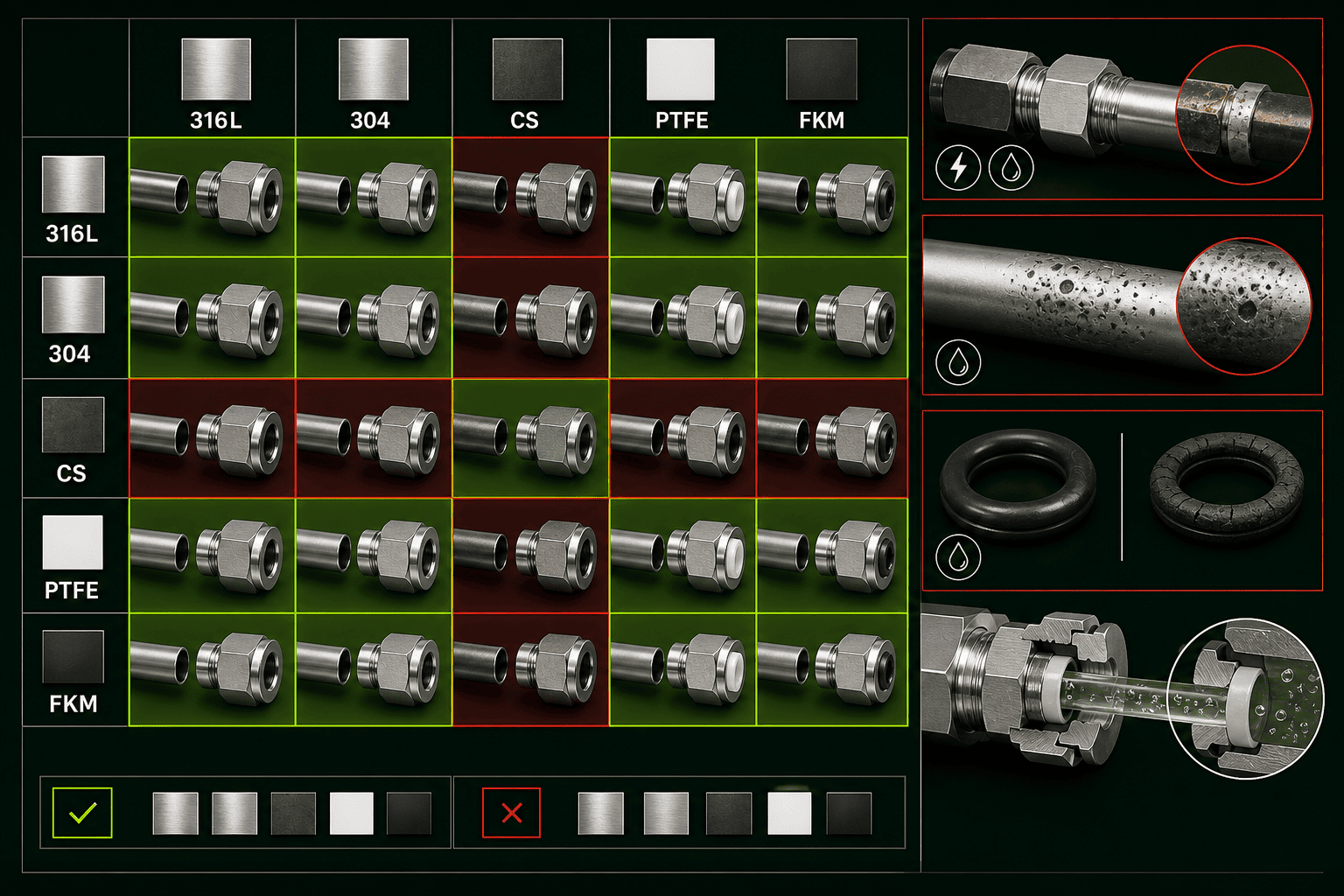
Fitting material must be matched to the tube material, the process media, and the operating environment. A material pairing that looks acceptable at procurement can generate galvanic corrosion, stress corrosion cracking, or media degradation that produces a leak after extended service.
Cause 7: Galvanic Corrosion from Dissimilar Metals
When two dissimilar metals are in electrical contact in the presence of a conductive medium — including moisture — galvanic corrosion begins7. The less noble metal corrodes preferentially.
A common example: using carbon steel fittings with stainless steel tubing, or vice versa. Both materials may be "stainless" on the certificate, but 304 SS and 316 SS have different corrosion resistance profiles in chloride-rich environments8. In aggressive service, fitting and tube material should match — not just approximately, but specifically.
Procurement action: Specify material grade, not just material family. "Stainless steel" is not a complete specification. Request material test reports (MTRs) and verify them before use in critical service.
Cause 8: Media Incompatibility with Elastomers or Seals
Many tube fittings in valve bodies, regulators, or face-seal configurations include elastomeric seals or soft seat materials. These materials have specific compatibility limitations with process media — particularly solvents, acids, oxidizers, and high-temperature fluids.
Selecting a fitting or valve with the wrong seal material for the process fluid produces a seal that degrades in service, swells, hardens, or loses elasticity — all of which eventually cause leaks. This is a system design decision that belongs in the specification phase, not the troubleshooting phase.
Do Operating Conditions Cause Tube Fittings to Leak?
A fitting can be correctly specified, correctly installed, and made from the right materials — and still leak. If the operating conditions exceed the fitting's rated envelope, no amount of installation care prevents the failure. In my conversations with customers, this cause is often the hardest to accept because the fitting "was fine" initially.
Tube fittings are rated for specific pressure, temperature, and media conditions. Operating continuously at or beyond those limits — or subjecting the fitting to repeated pressure spikes, thermal cycles, or vibration — degrades the seal geometry over time and produces leaks that were not present at initial make-up.
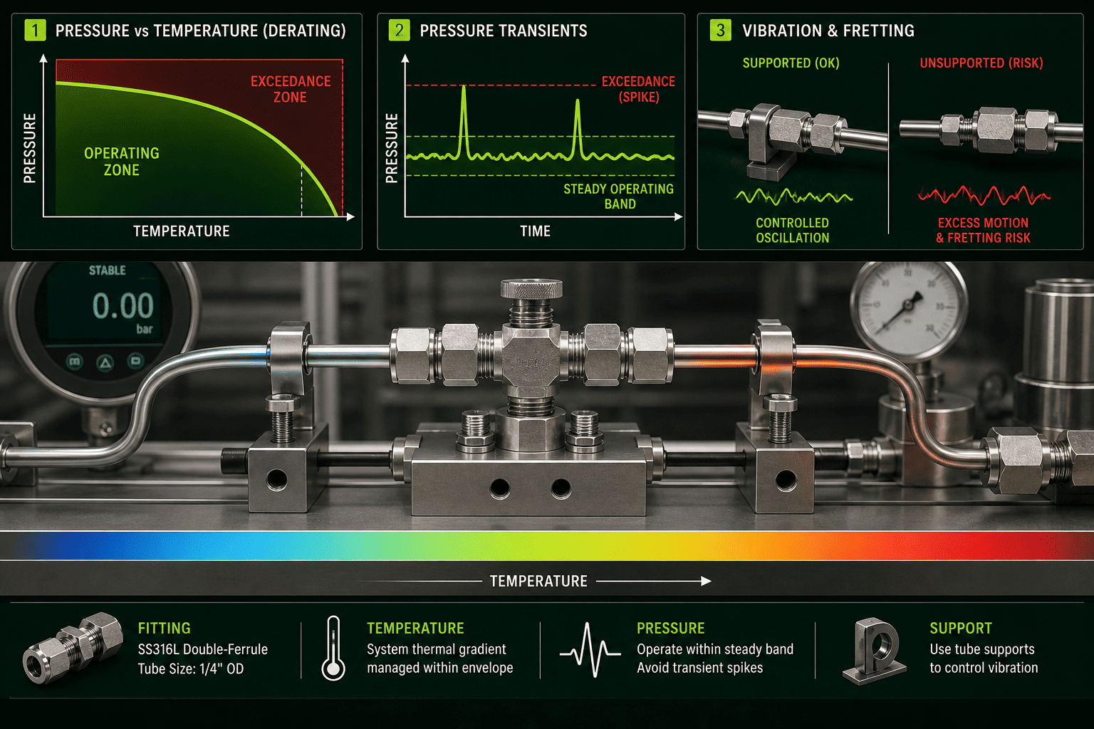
Cause 9: Pressure Spikes and Thermal Cycling Beyond Rated Conditions
Fitting pressure ratings are typically stated as maximum working pressure at a reference temperature (often 20°C or 70°F). At elevated temperatures, pressure ratings derate — sometimes significantly9. A fitting rated at 10,000 psi at ambient may be rated for considerably less at 300°C10.
Customers in heat-traced or steam-jacketed systems sometimes overlook this derating. They select a fitting based on the ambient-temperature pressure rating and discover the margin disappears at operating temperature.
Pressure spikes deserve separate attention. Hydraulic shock, pump start-up surges, and valve closure transients can generate instantaneous pressures well above steady-state operating pressure11. Repeated exposure fatigues the ferrule bite and gradually loosens the seal.
Before specifying, ask these questions:
- What is the maximum operating pressure, including transients?
- What is the maximum operating temperature at that pressure?
- Is the system subject to thermal cycling? How many cycles per day?
- Does the fitting supplier provide a derated pressure-temperature curve?
Cause 10: Vibration Fatigue in Dynamic Systems
Vibration is a long-duration degradation mechanism. A fitting installed on a vibrating pump, compressor, or reciprocating equipment experiences continuous micro-movement at the ferrule-tube interface. Over time, this fretting loosens the mechanical seal12 and allows the fitting to weep.
The solution is not to over-tighten. Over-tightening creates its own set of failures. The correct response is vibration-specific component selection: fittings designed for dynamic service, proper tube support and clamping to reduce transmitted vibration amplitude, and periodic inspection intervals appropriate to the vibration severity.
Frequently Asked Questions
How many turns does it take to properly make up a compression tube fitting?
The standard initial make-up for most compression tube fittings is finger-tight plus 1.25 turns of the nut. This applies to the first installation only. The exact specification may vary slightly by manufacturer and tube size — always confirm with the fitting supplier's installation documentation before proceeding.
Can I reuse a compression tube fitting ferrule after disassembly?
No. Compression ferrules are single-use components. Once swaged during initial installation, the ferrule geometry is permanently deformed to match the specific tube and fitting combination. Reusing a ferrule rarely reproduces the original seal and significantly increases the risk of leaks.
How do I know if my tube OD is compatible with the fitting I've ordered?
Verify the dimensional standard explicitly. Confirm whether the fitting is designed for inch-OD or metric-OD tubing, and check that your tube's actual outside diameter matches — not just its nominal size. A 1/4-inch fitting and a 6 mm fitting are not interchangeable despite similar nominal sizes.
What is the most common reason tube fittings leak in new installations?
Based on the support inquiries we receive most frequently, under-compression of the ferrule during installation is the leading cause of leaks in new systems. Most installation errors trace back to technicians tightening by feel rather than following the rotation-count procedure specified by the fitting manufacturer.
Should fitting material always match tube material?
In most instrumentation and process applications, matching fitting and tube material by grade — not just family — is the safer default. Using mixed or dissimilar metals introduces galvanic corrosion risk that may not manifest until the fitting has been in service for an extended period. For critical service, verify material pairing with your engineering team or fitting supplier.
Conclusion
Tube fitting leaks are almost always preventable — and the prevention happens before the fitting is installed, not after the leak is found. The ten causes covered in this article fall into three categories: installation errors (especially ferrule under-compression), specification mismatches (tube OD, wall thickness, and material), and system design risks (operating beyond rated pressure, temperature, or vibration conditions). Installation errors, particularly the 1.25-turn rule, are the highest-frequency cause in my experience. Tube OD mismatch is the most surprising. Both are procurement-stage checkpoints.
If you're specifying tube fittings for an upcoming project and want to verify compatibility before you order — or if you're evaluating a supplier and want to understand their quality and technical support capabilities — contact the Seewaylok or GOOLOK team. We're here to help you get the selection right the first time.
"Root cause analysis for 316L stainless steel tube leakages", https://www.academia.edu/50569725/Root_cause_analysis_for_316L_stainless_steel_tube_leakages. Quality control in modern tube fitting manufacturing has reduced defect rates, with field failure investigations more commonly identifying installation errors, material selection issues, or operating condition exceedances as root causes. Evidence role: general_support; source type: research. Supports: Manufacturing quality versus installation and specification factors in fitting failures. Scope note: This reflects general industry experience rather than comprehensive statistical analysis across all fitting manufacturers and applications ↩
"Failure analysis of an elbow tube fitting - UNT Digital Library", https://digital.library.unt.edu/ark:/67531/metadc71799/. Failure analysis studies of tube fitting leaks identify multiple contributing factors including improper installation, material incompatibility, and specification mismatches, though the relative frequency of each cause varies by industry and application. Evidence role: general_support; source type: research. Supports: Root cause distribution in tube fitting failures. Scope note: Comprehensive industry-wide statistics on tube fitting failure causes are limited, and failure distributions vary significantly across different industrial sectors ↩
"The HYPER lab tube fitting guide", https://hydrogen.wsu.edu/2016/10/10/the-hyper-lab-tube-fitting-guide/. Industry installation standards for compression-type tube fittings commonly specify finger-tight plus a defined rotation count to achieve proper ferrule swaging, though exact specifications vary by manufacturer and fitting design. Evidence role: general_support; source type: research. Supports: Standard installation procedures for compression tube fittings typically specify rotation-based make-up methods. Scope note: The precise 1.25-turn specification may vary by manufacturer, tube size, and fitting design rather than being universal across all compression fittings ↩
"The HYPER lab tube fitting guide", https://hydrogen.wsu.edu/2016/10/10/the-hyper-lab-tube-fitting-guide/. Compression tube fittings achieve sealing through controlled plastic deformation of the ferrule, which creates both radial compression against the tube and axial force against the fitting body through geometric interference. Evidence role: mechanism; source type: research. Supports: The sealing mechanism in compression tube fittings relies on controlled ferrule deformation. ↩
"Can You Reuse a Compression Fitting? Expert Guide", https://www.esg-intl.com/feeds/blog/can-reuse-compression-fitting. Tube fitting manufacturers generally recommend against reusing compression ferrules after disassembly, as the permanent deformation during initial swaging prevents reliable resealing in subsequent installations. Evidence role: general_support; source type: research. Supports: Industry guidance on ferrule reuse in compression tube fittings. ↩
"Compression Fitting Dimensions: Ultimate Sizing Guide", https://cntopa.com/compression-fitting-dimensions-ultimate-sizing-guide.html. Compression tube fittings are manufactured to tight dimensional tolerances, and tube OD variations beyond the fitting's design envelope can prevent proper ferrule compression and sealing. Evidence role: general_support; source type: research. Supports: Dimensional compatibility requirements between tube OD and compression fittings. Scope note: The specific threshold at which dimensional mismatch causes failure depends on fitting design, ferrule material, and tube wall thickness ↩
"Galvanic corrosion", https://en.wikipedia.org/wiki/Galvanic_corrosion. Galvanic corrosion occurs when two dissimilar metals are electrically connected in the presence of an electrolyte, causing accelerated corrosion of the more anodic (less noble) metal through electrochemical potential differences. Evidence role: mechanism; source type: encyclopedia. Supports: The electrochemical mechanism of galvanic corrosion between dissimilar metals. ↩
"SAE 316L stainless steel", https://en.wikipedia.org/wiki/SAE_316L_stainless_steel. Type 316 stainless steel contains molybdenum (2-3%), which provides superior resistance to pitting and crevice corrosion in chloride-containing environments compared to type 304 stainless steel. Evidence role: general_support; source type: research. Supports: Comparative corrosion resistance of 304 and 316 stainless steel alloys. ↩
"NPT Thread Pressure Ratings: Calculate ASME Fitting ...", https://industrialmonitordirect.com/blogs/knowledgebase/npt-pressure-ratings-asme-b1611-fitting-class-selection-guide?srsltid=AfmBOopRTQjiUiLxcNJvqjWkdPcMab4Nat3ZBoCVA-bvl4ryGPXEHwkJ. Pressure ratings for tube fittings and pressure vessels decrease with increasing temperature due to reduced material yield strength and creep resistance at elevated temperatures, following established pressure-temperature rating curves. Evidence role: general_support; source type: research. Supports: Temperature effects on pressure ratings of mechanical fittings. ↩
"300 Series Stainless Steel", https://www.cumberlandmetals.com/stainless-steel/300-series-austenitic-alloys/. Stainless steel alloys experience significant reduction in allowable stress values at temperatures above 200°C, with typical reductions of 30-50% at 300°C compared to ambient temperature ratings. Evidence role: general_support; source type: research. Supports: Material strength reduction at elevated temperatures affecting pressure ratings. Scope note: Exact derating depends on specific alloy composition, fitting design, and applicable design code ↩
"Hydraulic shock", https://en.wikipedia.org/wiki/Hydraulic_shock. Hydraulic transients such as water hammer can generate pressure spikes several times greater than steady-state operating pressure, with magnitude dependent on fluid velocity change, pipe characteristics, and valve closure rate. Evidence role: mechanism; source type: research. Supports: Pressure surge generation in fluid systems during transient events. ↩
"Fretting wear of heat exchanger tubes (Conference)", https://www.osti.gov/biblio/6699017. Fretting wear occurs at mechanical interfaces subjected to small-amplitude oscillatory motion, causing progressive surface degradation and potential loosening of compression-type connections through material removal and oxide formation. Evidence role: mechanism; source type: research. Supports: Fretting wear mechanisms in mechanical connections under vibration. ↩
Engineered to Seal.
Ready to Deliver.
Submit your Bill of Materials (BOM), system pressure parameters, or CAD drawings. Our engineering team can review your requirements and provide technical quotations with available material documentation.