
Double Ferrule Tube Fitting Installation: What’s Actually Causing Your Leak
This technical document outlines the critical tolerances, assembly sequences, and diagnostic practices for high-pressure fluid instrumentation systems manufactured to industrial standards.
Double Ferrule Tube Fitting Installation: What's Actually Causing Your Leak?
The calls we receive about leaking double ferrule tube fittings almost always trace back to one of two things — and neither of them is a defective product. If you're troubleshooting a leak right now, the frustration is real: you've tightened the fitting, the system is pressurized, and fluid or gas is escaping from a connection that looked perfectly assembled.
Most double ferrule tube fitting leaks are not product defects. They are installation errors. The two highest-frequency causes are incomplete tube insertion — where the tube end never contacts the internal tube stop — and incorrect make-up turns, where the nut is either under-tightened or over-tightened relative to the hand-tight baseline. Both errors are preventable with a step-by-step installation check before pressurization.
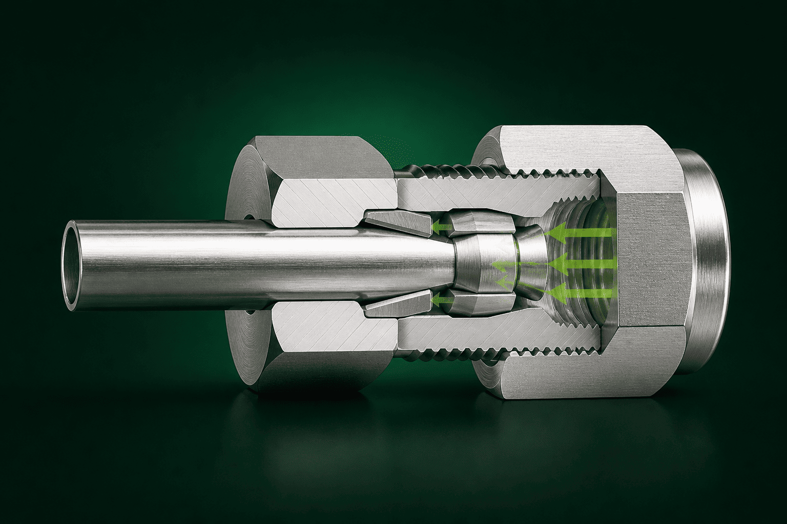
Understanding why these two errors happen — and how to catch them before they cause a leak — requires looking at the mechanics of how a compression fitting actually creates a seal. The details below are based on the pattern of complaints and troubleshooting calls our technical support team handles across OEM, system integrator, and instrumentation buyer segments.
Is Your Tube Fully Inserted Into the Fitting Body?
Incomplete tube insertion is the most common double ferrule fitting installation error we see, and it's also the most deceptive. The fitting looks assembled correctly from the outside. Nothing appears wrong until the system is pressurized and a leak appears at the connection.
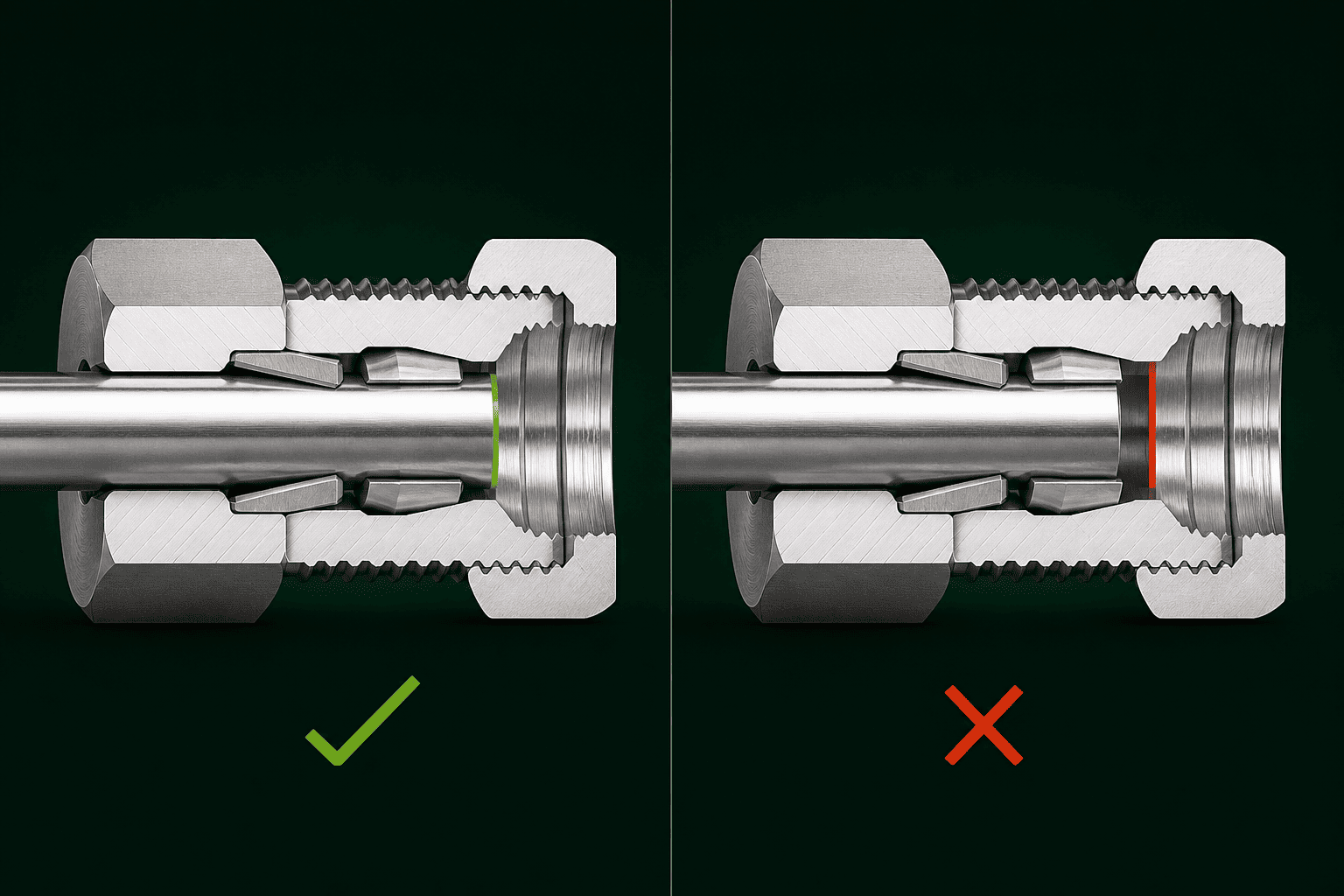
The fitting looks complete from the outside when the tube is not fully bottomed. The tube end must physically contact the internal tube stop inside the fitting body before you begin tightening. If the tube stops short — even by a millimeter or two — the ferrules will not compress against the correct section of tube wall, and the seal will be compromised or absent entirely.
The reason this error survives visual inspection is simple: the tube passes through the nut and ferrules before entering the fitting body, so the gap between the tube end and the tube stop is completely hidden. You cannot see it. You have to feel it — and follow a deliberate insertion procedure before you pick up a wrench.
What "Fully Bottomed" Actually Means
Inside every double ferrule fitting body, there is a machined internal shoulder called the tube stop. This is the physical reference point that the entire make-up procedure depends on. When the tube is pushed firmly forward until it contacts this stop, the front and back ferrules are positioned correctly relative to the tube OD and the fitting's internal geometry.
When the tube stops short:
- The front ferrule contacts a section of tube that wasn't intended for the compression zone
- The back ferrule cannot transmit force correctly to drive the front ferrule inward1
- The resulting seal — if any — is unreliable under pressure cycling and vibration2
How to Verify Tube Bottoming Before Tightening
Customers often tell us they "inserted the tube until it felt snug." That description almost always means the tube stopped at resistance — not at the tube stop. Here is a reliable procedure:
- Slide the nut and ferrules onto the tube in the correct order: nut first, then back ferrule, then front ferrule.
- Insert the tube into the fitting body with a firm, continuous forward push.
- While holding forward pressure on the tube, rotate the tube slightly back and forth. When the tube end contacts the tube stop, rotation resistance changes noticeably.
- Maintain that forward pressure as you hand-tighten the nut. Do not allow the tube to pull back while you are threading the nut.
This last point matters more than most installers realize. Threading the nut applies a slight rearward pull on the tube assembly. If you don't maintain forward tube pressure during hand-tightening, the tube can back away from the stop by 1–2 mm — and you won't know it happened3.
Are You Starting From the Right Hand-Tight Position?
The standard make-up specification for double ferrule tube fittings is hand-tight plus 1¼ turns4. This is widely documented and widely misapplied. In our technical support experience, the number of turns gets attention but the starting position — snug hand-tight — is routinely treated as optional. It is not optional. It is the reference point the entire specification depends on.
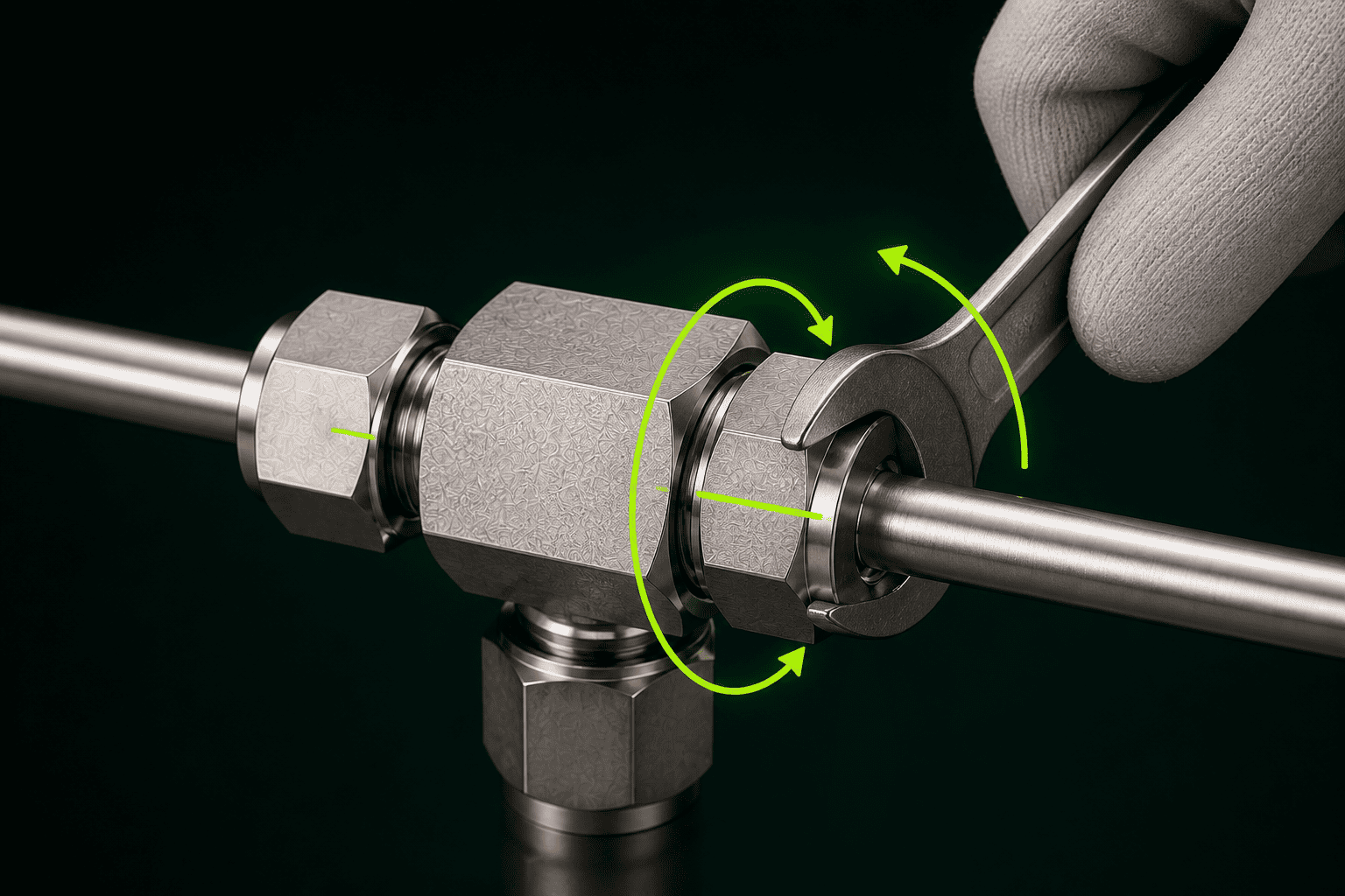
"Hand-tight plus 1¼ turns" means: tighten the nut by hand until it is snug — no wrench, no forcing — then apply exactly 1¼ turns with a wrench from that snug position. Under-tightening leaves insufficient ferrule bite and a leak path. Over-tightening deforms the ferrule or collapses the tube wall, which also creates a leak path and prevents re-make-up from sealing correctly.
Both failure directions — too few turns and too many — produce leaks, but they produce different kinds of leaks and different downstream problems. Understanding the difference helps you diagnose what actually went wrong.
Under-Tightening: Not Enough Ferrule Bite
When the nut doesn't reach the full 1¼ turns from hand-tight, the front ferrule has not been driven far enough forward into the fitting body. The ferrule's leading edge has not fully contacted and compressed against the tube OD. The result is a sealing surface with insufficient contact area or contact force — one that may appear to hold at low pressure but weeps or blows out when system pressure increases or when thermal cycling expands and contracts the tube5.
Signs of under-tightening:
- Leak appears immediately on pressurization
- Leak is intermittent, worsening under higher pressure
- Nut can be rotated slightly further by hand after a leak is detected
Over-Tightening: Deformed Ferrule, Damaged Tube
Over-tightening is less common as a first-time installation error, but it happens when an installer uses excessive wrench force to "make sure it's tight." Beyond the correct make-up position, additional turns push the ferrule further than the geometry was designed for. This can:
- Deform the front ferrule's sealing geometry
- Collapse or score the tube wall beneath the ferrule compression zone
- Create an irregular or damaged sealing surface that leaks under pressure fluctuation
The more significant consequence of over-tightening is that it eliminates the re-make-up margin. A correctly made-up fitting can typically be disassembled and re-tightened once in the same body with additional turns6, if needed. An over-tightened fitting has consumed that margin — and the ferrule or tube may be permanently unusable.
Using a Reference Mark to Control Turn Count
The most reliable method for controlling make-up turns in the field is the reference mark method:
- Reach hand-tight on the nut
- Use a marker to draw a line across the nut flat and onto the fitting body
- Apply 1¼ turns — which moves the mark 1¼ positions around the hex geometry
- Stop when the mark has traveled the correct arc
This method is especially useful when working in congested panel or manifold areas where visual access to the fitting is limited.
What About Re-Assembly? Is It the Same Procedure?
One installation scenario that generates its own category of leaks is re-assembly — disassembling a double ferrule fitting and reconnecting it, whether on the same tube or a new one. This situation has different rules from initial make-up, and customers sometimes apply initial make-up procedure to a re-assembly situation, with predictable results.
Ferrules are single-use compression components7. Once a ferrule has been swaged onto a tube — driven into its permanent set position during initial make-up — it has conformed to that specific tube OD and surface. If you remove the tube, discard the ferrule, and use a new ferrule, you are back to initial make-up procedure. But if you attempt to reuse a pre-swaged ferrule on a new tube, or in a new fitting body, the ferrule's geometry will not match the new contact surfaces, and the seal will be unreliable.
For re-make-up on the same tube in the same body, the procedure changes. You are not tightening 1¼ turns from hand-tight — you are tightening from the point where the nut contacts resistance (the pre-swaged ferrule's resting position) and applying a smaller additional turn. The specific re-make-up increment depends on the fitting manufacturer's specification. Do not assume the initial make-up turn count applies.
Key boundaries to keep straight:
| Scenario | Ferrule Condition | Procedure |
|---|---|---|
| First-time installation | New ferrule | Hand-tight + 1¼ turns |
| Re-make-up, same tube + body | Pre-swaged ferrule | Manufacturer's re-make-up spec |
| New tube, existing fitting body | New ferrule required | Hand-tight + 1¼ turns |
| Reused ferrule on new tube | Do not reuse | Replace ferrule |
Frequently Asked Questions
How do I know if my tube fitting leak is a product defect or an installation error?
In our technical support experience, the first diagnostic question is always installation procedure — not batch number. Before suspecting a product defect, verify that the tube was fully bottomed against the internal tube stop and that exactly 1¼ turns from hand-tight were applied. The large majority of field leaks resolve after correcting one of these two steps.
Can I re-tighten a leaking double ferrule fitting to fix the leak?
If the fitting was under-tightened during initial make-up, additional tightening from the current nut position may resolve the leak — but verify that the tube is still fully bottomed first. If the fitting was correctly made up, do not apply additional turns. Disassemble, inspect the ferrule and tube, and reassemble with fresh components if the sealing surfaces are compromised.
What tube preparation is required before installing a double ferrule fitting?
The tube end must be cut square — not at an angle — and deburred both on the OD and ID8. A beveled or burred tube end prevents full contact with the tube stop and creates an irregular sealing surface at the front ferrule interface. Use a proper tube cutter rather than a hacksaw for clean, square cuts9.
Does tube material affect how many make-up turns are required?
The 1¼-turn standard applies to typical stainless steel and carbon steel instrument tubing within the fitting's rated tube OD range. Softer materials like copper or aluminum may require fewer turns because the tube wall deforms more easily under ferrule compression10. Always check the fitting manufacturer's specification for the specific material combination you are working with.
Can I use a double ferrule fitting that was previously installed on a different tube?
The fitting body can be reused if it is undamaged and within specification. The ferrules cannot be reused on a different tube. Pre-swaged ferrules have conformed to their original tube's OD. Reusing them on a new tube will produce a mismatched sealing geometry and an unreliable connection. Replace ferrules when changing tube.
Conclusion
Most double ferrule tube fitting leaks are self-diagnosable installation problems. The two errors to check first are always the same: the tube was not fully bottomed against the internal tube stop, or the make-up nut was not tightened to the correct 1¼ turns from a snug hand-tight baseline. Both errors are invisible in the assembled fitting and both are preventable. Re-assembly errors — particularly reusing pre-swaged ferrules on new tubes — represent a separate failure mode worth eliminating from your field procedures.
If you are evaluating double ferrule tube fittings for an OEM build, a skid assembly, or a system integration project and want installation guidance specific to your tubing material and application, our technical support team at Seewaylok and GOOLOK is available to help. Reach out before your first installation — not after the first leak.
"What are Dual Ferrule Instrumentation Fittings?", https://www.titanfittings.com/articles/what-are-dual-ferrule-instrumentation-fittings?srsltid=AfmBOoqwQ9LoCqtNUOYbaLUJ6pkpGvo4bL6VEOBDZIX5TDNrf_Z24RZ1. In the double ferrule design, the back ferrule functions primarily as a force-transmitting and tube-gripping element, converting nut torque into axial load that drives the front ferrule into the fitting body taper to create the primary pressure seal against the tube OD. Evidence role: mechanism; source type: research. Supports: That in a double ferrule compression fitting, the back ferrule acts as a driving element that transmits nut rotation into axial force on the front ferrule, which creates the primary tube seal. Scope note: Detailed mechanical analysis of ferrule force transmission is largely documented in manufacturer engineering literature and patent disclosures rather than independent peer-reviewed publications. ↩
"Mitigating Instrument Tubing Failures | PDF", https://www.scribd.com/document/466075012/JFETOctober16Art01. Mechanical vibration subjects compression fitting connections to cyclic loading that can progressively reduce contact stress at the ferrule-tube interface; fittings with marginal initial make-up are more susceptible to vibration-induced seal degradation than correctly assembled connections. Evidence role: mechanism; source type: research. Supports: That mechanical vibration can degrade the seal integrity of compression tube fittings, particularly those with insufficient ferrule bite from under-tightening. Scope note: Published vibration testing data for double ferrule fittings is primarily found in manufacturer qualification reports rather than independent academic literature; failure thresholds depend heavily on vibration frequency, amplitude, and fitting configuration. ↩
"Chapter 5 Insert Nasogastric and Feeding Tubes - NCBI - NIH", https://www.ncbi.nlm.nih.gov/books/NBK594494/. Installation procedures published by double ferrule fitting manufacturers commonly instruct assemblers to maintain forward tube pressure during nut hand-tightening, acknowledging that the threading action can impart a rearward force component that displaces the tube from the tube stop prior to ferrule engagement. Evidence role: mechanism; source type: institution. Supports: That nut threading during hand-tightening can impart rearward axial force on the tube assembly, potentially displacing the tube end from the tube stop before ferrule make-up is complete. Scope note: The 1–2 mm displacement figure cited in the article is not directly sourced; actual displacement magnitude depends on thread pitch, nut geometry, and tube-to-bore clearance, and may vary across fitting sizes and manufacturers. ↩
"A Practical Guide to Instrument Tubing and Fitting Installation", https://zeroinstrument.com/eliminating-headaches-a-practical-guide-to-instrument-tubing-and-fitting-installation/. Major double ferrule fitting manufacturers, including those whose installation instructions are widely adopted as de facto industry practice, specify a make-up of 1¼ turns from the hand-tight position for initial assembly of standard stainless steel instrument tubing connections. Evidence role: expert_consensus; source type: institution. Supports: The 1¼-turn from hand-tight make-up specification for double ferrule compression tube fittings. Scope note: The exact turn count may vary by manufacturer and tube OD; this figure reflects common practice rather than a single codified international standard. ↩
"How Industrial Instrumentation Fittings Prevent Downtime", https://www.nwindustrialservice.com/post/industrial-instrumentation-fittings-case-study. Differential thermal expansion between tube and fitting body materials, combined with repeated temperature cycling, can alter contact stress at the ferrule sealing interface; fittings with insufficient initial ferrule bite are particularly susceptible to seal degradation under such cyclic loading. Evidence role: mechanism; source type: research. Supports: That thermal cycling induces dimensional changes in tube and fitting components that can expose marginal seals in under-tightened compression fittings to leak paths. Scope note: Quantitative failure data specific to under-tightened double ferrule fittings under thermal cycling is limited in open literature; the mechanism is supported by general principles of contact mechanics and thermal expansion. ↩
"Double Ferrule Compression Fittings", https://favfittings.com/instrument-fittings/double-ferrule-compression-fittings/. Fitting manufacturer installation guidelines generally permit re-make-up of double ferrule connections on the same tube and body a limited number of times, with the re-make-up procedure differing from initial make-up in the turn increment applied from the resistance point. Evidence role: general_support; source type: institution. Supports: That double ferrule fittings permit a limited number of re-make-up cycles on the same tube and body before reliability is compromised. Scope note: The permissible number of re-make-up cycles is manufacturer-specific and may also depend on tube material and service conditions; this claim should be verified against the specific product's technical documentation. ↩
"Swaging", https://en.wikipedia.org/wiki/Swaging. During initial make-up, the ferrule undergoes plastic deformation—commonly termed swaging—conforming its geometry to the specific tube OD and fitting body taper; this permanent set means the ferrule cannot form a reliable seal against a different tube surface. Evidence role: mechanism; source type: research. Supports: That ferrules undergo permanent plastic deformation during initial make-up, rendering them unsuitable for reuse on a different tube or fitting body. Scope note: Direct experimental studies on ferrule reuse failure rates are limited in open literature; this claim is primarily supported by manufacturer technical documentation and materials engineering principles. ↩
"Copper Compression Fittings: A Complete Installation Guide", https://brassland.com/resources/blog/copper-compression-fittings-a-complete-installation-guide.html. Standard installation guidance for compression tube fittings specifies that tube ends must be cut perpendicular to the tube axis and deburred on both the outer and inner diameters, as angular cuts or burrs prevent full tube stop contact and introduce leak paths at the front ferrule sealing interface. Evidence role: expert_consensus; source type: institution. Supports: That square tube end cuts and complete deburring of both OD and ID are required for reliable compression fitting seals. Scope note: This reflects widely adopted installation practice documented by major fitting manufacturers; a single codified international standard governing all compression fitting tube preparation does not appear to exist. ↩
"Hack saw vs tube cutter for steering tube", https://www.bikeforums.net/bicycle-mechanics/1161628-hack-saw-vs-tube-cutter-steering-tube.html. Installation guidelines from fitting manufacturers and instrumentation standards bodies consistently recommend rotary tube cutters over abrasive or toothed cutting methods, citing the superior squareness and reduced burr formation of cutter-produced tube ends as critical to reliable ferrule seating. Evidence role: general_support; source type: institution. Supports: That rotary tube cutters produce more consistently square and burr-free tube ends than hacksaws for compression fitting installation. Scope note: Comparative cut quality data between cutting methods is largely found in manufacturer application notes rather than independent peer-reviewed studies. ↩
"The HYPER lab tube fitting guide", https://hydrogen.wsu.edu/2016/10/10/the-hyper-lab-tube-fitting-guide/. Fitting manufacturers typically publish material-specific make-up specifications, with softer tube materials such as copper and aluminum requiring reduced turn counts relative to stainless steel due to their lower yield strength and greater susceptibility to plastic deformation under ferrule compression. Evidence role: mechanism; source type: institution. Supports: That tube material hardness affects the required make-up turn count for double ferrule compression fittings. Scope note: Specific turn count values vary by manufacturer and tube OD; the general principle is well-established but precise figures require consultation of the applicable product installation guide. ↩
Engineered to Seal.
Ready to Deliver.
Submit your Bill of Materials (BOM), system pressure parameters, or CAD drawings. Our engineering team can review your requirements and provide technical quotations with available material documentation.